Concept & Design Background
During the late 1950’s, I attended a most unique high school. It had all the expected college prep courses, but because of the terms of its founding endowment, all students were required to take wood, metal, machine, and electric shop. If you desired you could take up to 4 years of each. The school was so successful with this program that during WWII it machined the wind screens (nose cones) for anti-aircraft shells! Because of this, we had an exceptionally well equipped machine shop. When several of us wanted to pursue advanced projects concerning firearms, it was not considered at all unusual – how times have changed!
Around 1957, I read articles concerning a cartridge call the 22 JGR. If I remember correctly, it was basically a 32 ACP necked down to .22 caliber. It had a short life, but really made a great impression on me. I made some simple forming dies and formed a number of similar prototype cartridges. I still have several 25 ACP, 32 ACP, and 9mm cartridges necked down to various smaller calibers. Because few appropriate powders and even fewer small bullets were available, these never got beyond the day-dreaming stage (let alone the fact that special reamers were difficult to obtain and beyond the financial reach of a high school teenager). I retreated to my books by Julian Hatcher and Phillip Sharpe, but never lost interest in these strange miniature cartridges.
In the early 1960’s, I attended the University of California at Davis. Of course a selection of small arms came along. Jack rabbit and ground squirrel hunting was the order of the day. I also did some pistol smithing for the local gunsmith as his eyes were giving him trouble. During this period the .221 Fireball was introduced. The XP-100 pistol was beyond my financial reach, but with help from the old gunsmith, we converted an M1 Carbine to fire the round. This was not a simple conversion, and even though it worked, we were definitely pushing the capabilities of the little action. Once again the choice of appropriate powder and bullets was limited. My ideas were once again put aside for a future date.
40 years later I retired. I started to catch up on my firearms reading. I was excited to see the growing interest in small, highly efficient, and high velocity cartridges. There was now a very broad selection of powders and bullets, so I immediately decided to renew my pursuit of these little wonders. As usual, wildcatters developed a number of successful individual cartridges – I couldn’t wait!
In my business career, I spent a lot of time in product design, and had become a devout disciple of modular design principles. I was very curious to explore the concept using a single combustion chamber (read: cartridge case) to propel various bullets of different weights and calibers. I made lists of existing commercial and wildcat cartridges that showed potentially great accuracy, high efficiency, low noise and recoil, reasonably high velocity and easy forming. I also wanted to settle on a single case that was capable of being formed into multiple calibers, with the only difference being the neck diameter. After a lot of head scratching and hours playing “what If” with Quick Load, I kept coming back to my old friend, the 30 M1 Carbine. It has thick walls of a relatively modern design, and reasonable availability.
I read everything I could find on the 17 PeeWee and the 5.7mm Johnson (22 Spitfire) cartridges. I felt that both cartridges, particularly the 17 PeeWee were ahead of their times, and had suffered from a lack of appropriate components. I next laid out potential cartridge profiles in 2D AutoCad. Since it was obvious that reforming brass from 30 caliber all the way down to 17 would have to be done in several stages, it only made sense that each of these stages should yield a usable cartridge. The chart below shows the most logical progression.
I.D. Reduction from Caliber to Caliber
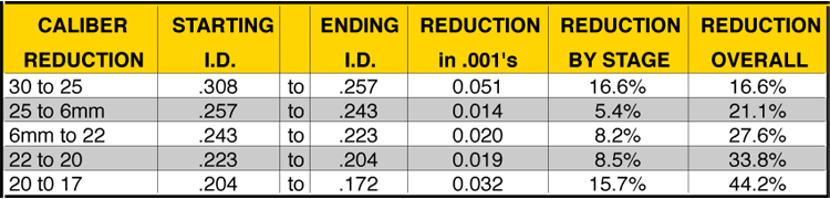
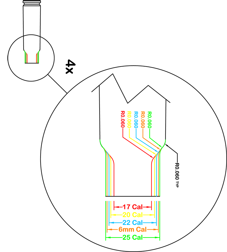
I wanted all the cartridge bodies to have the identical dimensions up to and including the shoulder. This would also allow the use of a single set of GO/NOGO gauges for all cartridges. It also yielded virtually identical internal capacities. Since the body length, shoulder angle, and overall case length were held constant in all calibers, the only variables were neck diameter and neck length. While this was not as important in the larger calibers because the shoulder was quite short, when the case was necked down to 20 and 17 caliber, a shallower angle produced an unacceptably short neck for proper bullet grip (tension). A 40° shoulder produced a good compromise, but raised a potential problem with pushing back a sharp shoulder during forming. It might also create feeding problems in repeating arms. An answer to both these concerns was found in increasing the radius of the junction between the body and the shoulder and between the shoulder and the neck to .060”. The resulting cases are easy to form with virtually no losses, and feed quite smoothly.
Typical Cartridges

Overlaying the individual cartridge outlines clearly displays the concept.
Cartridge Necks
Calculating Case Capacities
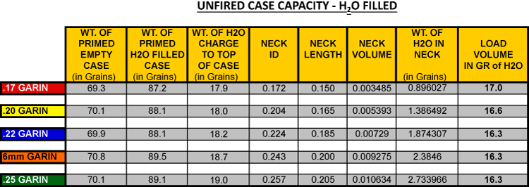
There are a number of valid ways to determine case capacity. I chose a simplified method since I felt this would allow me to do a lot of “what ifs” with good comparative data. The same process was used for both formed / unfired-formed, and formed / fire-formed cases. I first placed a fired primer in a case and weighed it dry. Next, I filled the case with water to the top of the mouth (try to get consistent menisci), and weighed wet. The total weight of water the cartridge will hold is now known. I now calculated the volume of the neck from the case mouth to the point where the neck goes tangent to the radius between the neck and the shoulder. This sounds complicated, but is an easily obtained dimension in the Cad drawings. The weight of this cylinder filled with water was now subtracted from the total weight of the filled case to yield the weight of water in Grains in the case body. I now had a good, consistent way of comparing cartridge body capacities. When final loads are being evaluated, this value can be fine tuned by adjusting the neck volume calculation to account for various seating depths.
The tables below show typical calculations.
Unfired Case Capacity — H2O Filled
If you don’t have easy access to dimensions, James Ristow of Recreational Software, Inc. has another, rather elegant, approach:
“If you do not own software that will calculate load densities there is a manual method that will work. First it is necessary to determine the powder capacity of the cartridge. To do this, file a small notch inside the mouth of a fired but not decapped case so it extends from the rim of the case to a point just beneath the bullet's base when it is seated. Weigh the case and bullet. Fill the case with water and carefully seat the bullet while displacing water out the notch filed in the mouth. Weigh the water filled case and bullet again. The difference in weights is the powder capacity of the cartridge in grains of water.”
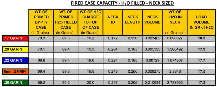
The chart below shows the same calculations after fire-forming.
Fired Case Capacity — H2O Filled — Neck Sized
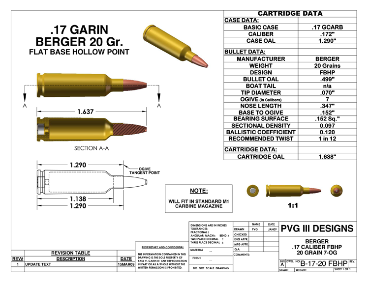
Once the basic cartridge configurations were determined, the drawings were rendered in SolidWorks (a 3-D cad program) to aid in discussions with other people interested in the project. See example below.
3D CAD Drawing
With the 3-D drawings now in hand, the main effort shifted to tooling and gun sourcing.